Vacuum forming is one of those manufacturing processes that looks straightforward until you try to do it well. A sheet of plastic goes in, heat is applied, vacuum pulls it into shape, and out comes a part. That's the short version. The longer version is where all the real engineering lives: picking the right temperature window, understanding how material moves under a vacuum, designing a mold that releases cleanly, and avoiding the wall thinning that kills deep-draw parts.
This guide walks through every stage of the process in the order you encounter it on the shop floor, with the specific numbers and decisions that actually matter.
What Is Vacuum Forming and How Does It Work?
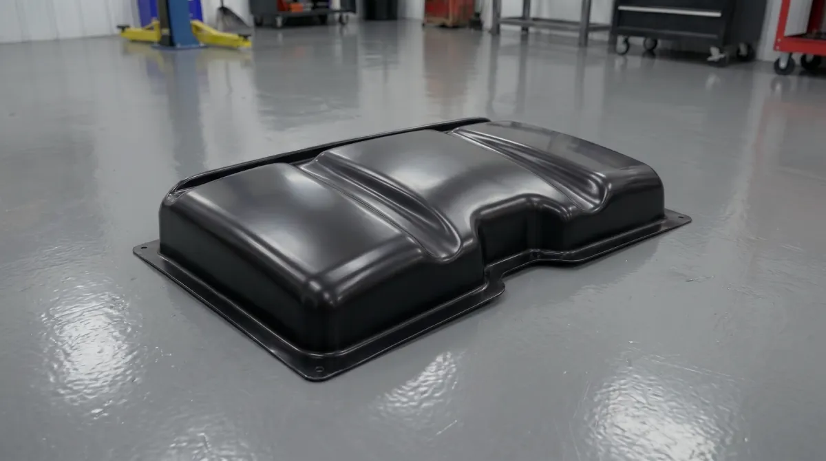
Vacuum forming is used to make the plastic parts you see everywhere: automotive dashboard panels, refrigerator liners, retail display stands, medical device housings, food packaging trays, and protective covers for industrial equipment. If a plastic part is large, thin-walled, and produced in moderate volumes, there's a good chance it came off a vacuum forming machine.
Vacuum forming is a subset of thermoforming. The fundamental principle is simple: you heat a thermoplastic sheet until it becomes pliable, bring it into contact with a mold, then evacuate the air between the sheet and the mold surface. Atmospheric pressure — about 14.7 psi at sea level — pushes the soft plastic into every contour of the tool.
What makes this different from injection molding is that the plastic never becomes a liquid. You're working in a narrow temperature band between the glass transition point (where the material starts to soften) and the melt point (where it loses structural integrity). For common materials like ABS and HIPS, this window is wide and forgiving — they're easy to work with. For semi-crystalline materials like polypropylene, the window is tighter and requires more precise control.
The pressure available to form the part is limited to atmospheric: one atmosphere, or roughly 1 bar. That's enough for clean detail on most surfaces, but not enough to replicate the sharp edges and deep texture you get from injection molding at 500–2,000 bar. When sharper detail is needed, vacuum is supplemented with compressed air on the opposite side — this is called pressure forming.
The Step-by-Step Vacuum Forming Process
The production cycle has six distinct phases, and each one directly affects part quality. Problems in the finished part almost always trace back to a specific phase where something went wrong.
Step 1: Sheet Clamping
The plastic sheet is loaded into a clamping frame around its perimeter. The frame has to hold the sheet firmly enough that it doesn't pull out of the clamp zone during forming, but not so aggressively that it cuts into the edge. For deep-draw parts, losing grip mid-form means an instant scrap. The material in the clamp zone doesn't form into the part — it becomes trim waste — so the frame is sized to leave an adequate flange around the part perimeter.
Step 2: Heating
Infrared heaters above (and sometimes below) the sheet raise its temperature into the forming zone. Heating from one side only is common for thin sheets under 3 mm, but thicker material benefits from dual-side heating to avoid a temperature gradient through the cross-section. If the surface heats faster than the core, the outer skin begins to degrade while the center is still too stiff.
Sag is the most visible sign that a sheet is ready. As the material softens, gravity pulls it into a controlled downward curve. Most operators use this sag as a visual cue: a downward bow of 25–50 mm on a medium-sized sheet typically indicates the material is ready. For automated machines, this is monitored with a laser or IR sensor.
Zone heating is used to compensate for edge cooling. The clamp frame acts as a heat sink, pulling energy away from the edges of the sheet. Heater zones near the perimeter run at higher output to keep the edge temperature consistent with the center.
Step 3: Pre-Stretching — Bubble or Plug Assist
For deep-draw parts, the sheet is pre-stretched before the mold engages. Two methods are common:
- Air bubble: Compressed air is blown under the sheet, raising it into a dome. This pre-distributes the material more evenly before the mold contacts it.
- Plug assist: A mechanical plug, typically machined from syntactic foam or aluminum, presses into the sheet from above before vacuum is applied. The plug physically moves material down into the cavity, preventing the excessive thinning at corners and the base that would otherwise occur.
Step 4: Forming
The mold moves into position and vacuum is applied. The evacuation time matters: too slow and the sheet cools before fully conforming to the tool; too fast and you can trap air between the plastic and the mold, leaving a web or blister on the surface. Vacuum holes on the mold surface are typically 0.4–0.8 mm in diameter — large enough to evacuate air quickly, small enough that they don't leave visible marks on the part.
Step 5: Cooling
The part must be cooled while still on the mold so it retains the formed geometry. Released too early, it springs back or warps as residual stresses redistribute. Cooling is done with ambient air, forced air, or water mist depending on cycle time requirements and material. ABS typically needs to cool to 65–75°C before safe demolding. Polycarbonate requires more time due to its high glass transition temperature — do not demold PC parts above 110–120°C.
Step 6: Demolding and Trimming
Once cooled, vacuum is released — and sometimes a small positive pressure pulse is applied to break the part free — and the sheet with the formed part is removed. The part is then separated from the trim flange. For low volumes, this is done with hand tools or a band saw. For production, CNC routers with 5-axis heads or robotic trimming cells are standard.
Which Plastics Work Best for Vacuum Forming?

Material selection is the decision that shapes everything else in the process. Each polymer has a different forming temperature, shrinkage rate, moisture sensitivity, and behavior under deep draw. Here's the data I work with when evaluating materials for a new project:
| Material | Forming Temp (°C) | Pre-Dry Temp / Time | Shrinkage (%) | Draw Ratio Limit | Typical Applications |
|---|---|---|---|---|---|
| ABS | 150–170 | 80°C / 3–4 h | 0.4–0.7 | 3.0:1 | Enclosures, automotive trim, housings |
| HIPS | 120–150 | Not required | 0.3–0.6 | 3.0:1 | Packaging, display, food trays |
| PETG | 130–160 | 65°C / 2 h (if required) | 0.2–0.5 | 2.5:1 | Medical, cosmetic, clear packaging |
| HDPE | 140–170 | Not required | 2.0–3.5 | 2.0:1 | Industrial parts, tanks, pallets |
| Polycarbonate | 175–205 | 120°C / 4–8 h | 0.5–0.7 | 2.0:1 | Glazing, safety shields, lighting |
| Acrylic (PMMA) | 150–180 | 80°C / 6–12 h | 0.2–0.4 | 2.0:1 | Displays, signs, light covers |
| Polypropylene | 155–175 | Not required | 1.5–2.2 | 1.5:1 | Automotive, living hinges, medical |
ABS is the default choice for technical parts. It has the widest forming window, accepts surface texture well, bonds easily for secondary operations, and machines cleanly after forming. If there's no specific reason to choose something else, ABS is where I start.
Polycarbonate and acrylic need extra attention before they go near the heater. Both absorb atmospheric moisture and will develop surface blistering and internal silver streaks if formed wet. Polycarbonate requires at least 4 hours at 120°C in a desiccant dryer before forming. Cutting that time short is one of the most reliable ways to produce scrap.
Polyolefins — PP and HDPE — are genuinely difficult to vacuum form well. Their crystalline structure means they soften and then go limp very quickly as temperature rises, with almost no warning. An air cushion under the sheet during heating is not optional: it's necessary to prevent the sheet from sagging onto the heater and burning. For a full breakdown of how each material behaves on the machine, see our guide on choosing the right plastic for vacuum forming. If you run into defects during forming, see the Vacuum Forming Troubleshooting Guide for root causes and fixes.
How Does Heating Work in a Vacuum Forming Machine?
Most vacuum forming machines use ceramic, quartz, or halogen infrared heaters. The choice matters because different heater types emit energy at different wavelengths, and different polymers absorb that energy at different efficiencies.
| Heater Type | Peak Wavelength (µm) | Response Time | Best For |
|---|---|---|---|
| Halogen (short-wave) | 1.0–1.2 | Instant | Thick sheets, fast cycling |
| Quartz (medium-wave) | 2.4–4.0 | 30–60 sec | Most thermoplastics |
| Ceramic (long-wave) | 4.0–10.0 | 10–15 min | Thin films, delicate materials |
Quartz heaters cover the 2–4 micron absorption range that most industrial thermoplastics respond to most efficiently. For general production, they're the right choice. Halogen heaters heat faster and penetrate thicker cross-sections better, but they can overheat the surface before the core catches up if the sheet is thick and the cycle time is aggressive.
Zone control is what separates a machine that produces good parts from one that produces consistent good parts. Independent heater zones, typically 25–50 mm square, allow the operator to compensate for the cold strip that forms near the clamp frame, apply more heat to areas that need more stretch, and correct for asymmetric geometry on the mold.
What Is Draw Ratio and Why Does It Matter for Wall Thickness?
Draw ratio is the relationship between the surface area of the formed part and the surface area of the flat sheet that produced it. A flat sheet that becomes a part with twice the surface area has a draw ratio of 2:1. The wall thickness of that part will be roughly half the original sheet thickness — because the same volume of material is now spread over twice the area.
This is the central engineering constraint in vacuum forming. Material doesn't redistribute itself evenly — it follows the path of least resistance. The first surfaces the plastic contacts cool faster and stop moving, while areas that contact the mold later continue to thin. The corners and the base of a deep box are almost always the thinnest points in a part.
Practical limits by material:
- ABS and HIPS: draw ratios up to 3:1 are achievable with plug assist. Beyond that, corner thinning becomes structural.
- PETG and polycarbonate: 2.5:1 maximum without specialized tooling.
- Polypropylene: 1.5:1 before thinning becomes excessive.
For any part with a draw ratio above 1.5:1, plug assist should be on the table. For parts above 2.5:1, it's essentially required unless you can redesign the geometry to reduce the depth.
Positive vs. Negative Molds: What Is the Difference?
The choice between a positive (male) mold and a negative (female) mold affects which surface of your part is dimensionally accurate, where the wall thinning occurs, and what draft angles you need.
Positive (Male) Molds
The plastic sheet drapes down over a convex tool. The inside surface of the part conforms precisely to the mold. The outside surface is formed by atmospheric pressure pushing against it, so it has less definition. As the part cools, it shrinks and grips the mold, which means draft angles are critical: minimum 3–5° on vertical walls. Without enough draft, the part locks onto the tool and demolding either deforms the part or damages the tool.
Positive molds are used when the inside surface geometry matters most: housings, covers, and enclosures where the internal contour needs to be accurate.
Negative (Female) Molds
The plastic is drawn into a concave cavity. The outside surface of the part is defined by the mold; the inside surface is less controlled. As the part cools, it shrinks away from the cavity walls, which actually helps with release. Draft angles of 3–5° are standard; on smooth surfaces without texture, 1.5–2° can be sufficient. Negative molds reproduce external surface detail better and are the standard choice when the appearance or dimensional accuracy of the outside surface is the priority.
Advanced Techniques: When Standard Vacuum Forming Isn't Enough
Pressure Forming
Pressure forming adds compressed air on the top side of the sheet while vacuum is applied below. The combined forming force typically reaches 2–6 bar, compared to the 1 bar available from vacuum alone. That additional pressure drives the plastic into sharper corners, finer texture details, and undercuts that vacuum alone can't reach. The results can approach injection molding surface quality. The trade-off is more complex tooling: a sealed upper box is needed to contain the pressure, and the machine has to be built to handle it.
Twin-Sheet Thermoforming
Two sheets are formed simultaneously on opposing molds, then pressed together before they cool. The result is a hollow, double-walled structure — rigid, lightweight, and able to incorporate internal channels, bosses, or enclosed volumes without a secondary bonding step. This is how fuel tanks, industrial pallets, and ventilation ducts are produced in thermoforming.
Plug Assist
Already mentioned in the process section, but worth a separate note: plug material matters. Rigid aluminum plugs transfer heat to the sheet on contact, which can cause localized stiffening before the form is complete. Syntactic foam plugs are the preferred choice because they're low-conductivity — they pre-stretch the sheet without cooling it. The plug temperature is typically set 10–15°C below the sheet forming temperature to minimize contact cooling.
Vacuum Forming vs. Injection Molding: When Each Makes Sense
Both processes make plastic parts. The decision comes down to volume, part size, lead time, and tooling budget.
| Factor | Vacuum Forming | Injection Molding | FDM 3D Printing |
|---|---|---|---|
| Tooling cost | $500–$10,000 | $10,000–$100,000+ | $0 |
| Tooling lead time | 2–4 weeks | 8–20 weeks | Hours to days |
| Per-part cost | Medium | Low (at volume) | High |
| Max part size | 3+ meters | Limited by press | Limited by bed |
| Surface detail | Good | Excellent | Moderate |
| Wall thickness control | Variable | Precise | Variable |
| Break-even volume | — | 3,000–5,000 units | Under 50 units |
For parts in the 50–3,000 unit range, vacuum forming almost always wins on economics. Above 5,000 units, the lower per-part cost of injection molding usually offsets the higher tooling investment. The crossover point depends on part complexity, but 3,000–5,000 units is the range where the comparison gets close.
Part size is often the deciding factor independent of volume. Injection molding has practical limits tied to press tonnage. Vacuum forming can produce parts several meters across with tools that cost a fraction of what steel injection molds cost. For large enclosures, covers, and panels, vacuum forming has no real alternative at comparable cost.
Mold Materials: What to Build Your Tool From

The mold is where most of the investment lives, and the right material depends on your production volume and part requirements.
Learn more about the materials used for making molds in vacuum forming in our article Vacuum Forming Mold Design: Complete Guide for Beginners.
- Machined aluminum. The standard for production tooling. Good thermal conductivity speeds cooling, it machines cleanly, and holds tight tolerances. An aluminum tool can run tens of thousands of cycles without degradation.
- Urethane or epoxy resin. Fast and cheap to produce from a plug. Suitable for prototyping and short runs under 500 parts. Thermal conductivity is poor, which extends cycle time.
- High-density foam (machined). The fastest option for concept validation. Not suitable for production — surface detail is limited and it degrades under heat.
- Wood or MDF. Used for non-critical prototype shapes. Limited life, absorbs heat unevenly, and can off-gas at forming temperatures.
For a new product where design changes are still likely, starting with a urethane tool and moving to aluminum once the geometry is locked makes financial sense. The cost difference between a urethane prototype tool and an aluminum production tool is typically 10x to 20x — spending that on a part that's going to change is a poor use of budget.
FAQ
What is vacuum forming used for?
Vacuum forming is used across a wide range of industries to produce plastic parts that are large, thin-walled, or needed in moderate volumes. Common applications include automotive interior panels and trunk liners, refrigerator and appliance inner liners, retail display stands and point-of-sale fixtures, medical device housings and trays, food packaging and blister packs, protective covers for industrial equipment, and signage. The process is especially competitive when part size is large, tooling lead time matters, or volumes are in the range of 50 to 5,000 units where injection molding tooling costs can't be justified.
What is the difference between vacuum forming and thermoforming?
Thermoforming is the broad category — any process that heats a plastic sheet and forms it over a mold. Vacuum forming is the most common type of thermoforming: it uses atmospheric pressure (created by evacuating air between the sheet and the mold) to push the plastic into shape. Pressure forming is another type of thermoforming that adds compressed air on the opposite side for more forming force and sharper detail. In everyday use, "thermoforming" and "vacuum forming" are often used interchangeably, but technically vacuum forming is one method within the thermoforming family.
Why does my vacuum formed part have uneven wall thickness?
Uneven wall thickness comes from uneven material distribution during forming. The areas that contact the mold first stop moving — friction and cooling lock them in place — while areas that contact the mold later continue to thin as the vacuum pulls them. The fix is usually plug assist for deep-draw geometry, or reconsidering the draw ratio if the part depth is pushing the material's limit. Check that heating is uniform before looking at the forming stage: cold spots in the sheet produce thick patches in the finished part.
What causes surface blistering or silver streaks in vacuum formed parts?
Almost always a moisture problem. ABS, polycarbonate, acrylic, and PETG absorb water from the air. When a wet sheet is heated rapidly, that moisture converts to steam and creates internal pressure — the result is bubbles or silver streaks under the surface. The fix is pre-drying: ABS at 80°C for 3–4 hours, polycarbonate at 120°C for 4–8 hours, acrylic at 80°C for 6–12 hours. Use a desiccant dryer, not a standard oven, to ensure the moisture is actually being removed rather than circulated.
How much draft angle does a vacuum forming mold need?
For positive (male) molds, the minimum is 3–5° on all vertical walls. The part shrinks onto the mold as it cools, so without adequate draft the part grips the tool and won't release without force. For negative (female) molds, 3–5° is standard; 1.5–2° can work on smooth surfaces without texture. Textured surfaces need more draft than smooth ones — add 1° per 0.025 mm of texture depth as a starting point.
What is the maximum draw ratio for vacuum forming?
For most materials, 2:1 is achievable without plug assist. With plug assist, ABS and HIPS can be pushed to 3:1, sometimes higher in controlled conditions. Beyond 3:1, wall thinning in the corners and base typically becomes severe enough to be a structural problem. If your part geometry requires a higher ratio, consider twin-sheet forming to create a hollow structure, or redesign the part to reduce depth.
Which is cheaper — vacuum forming or injection molding?
It depends on volume. Vacuum forming tooling costs between $500 and $10,000 for most parts. Injection mold tooling for the same part typically costs $10,000 to over $100,000. At low to medium volumes — roughly under 3,000–5,000 units — vacuum forming has a lower total cost. Above that threshold, the lower per-part cost of injection molding begins to compensate for the tooling investment. For large parts over 500 mm in any dimension, vacuum forming stays competitive at much higher volumes because injection molding tooling for large parts scales in cost much faster.
Related on the Blog
If you're running into defects during forming — webbing, warping, poor detail — the full diagnosis with fixes for 15 common problems is in our Vacuum Forming Troubleshooting Guide. To choose the right plastic for your application, see How to Choose the Right Plastic Sheet for Vacuum Forming. For machine costs and what to expect when budgeting, see Vacuum Forming Machine Price: What Industrial Machines Actually Cost. If you want a full buyer's guide, everything you need to know about selecting a machine is in our Buy Vacuum Forming Machine guide.
THERMOFORA Vacuum Forming Machines
Industrial vacuum forming machines — manufactured and ready to ship
From compact prototyping formats to full industrial sheet sizes. Every machine is built, tested, and shipped from our facility. Running in production across 24 countries.